Correct cutting and fitting of the Mayer stainless steel pipe system is essential to achieve air and watertight joints. The techniques and tools required for appropriately installed pipe systems are easily acquired and should be familiar to tradesmen who have worked with copper piping systems, with some special allowances for the specific properties of stainless steel. By following simple guidelines and using approved electronic tools, Mayer stainless steel pipe systems are rapidly implemented, deliver leak-free performance and will last the lifetime of the building.
PRESS FITTING GUIDELINES, TOOL USE & PREPARATION
Sizes 15, 22, 28 & 35
1
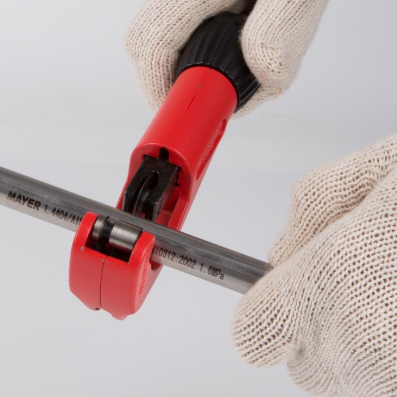
Cutting
Pipes are cut to length with approved burr-free cutters. Oxy-acetylene torches and abrasive cut-off wheels are not suitable. Pipes are cut at right angles to their axis, using a pipe cutter or fine-tooth saw. Measured lengths must take into account the depth of insertion into the fitting.
2
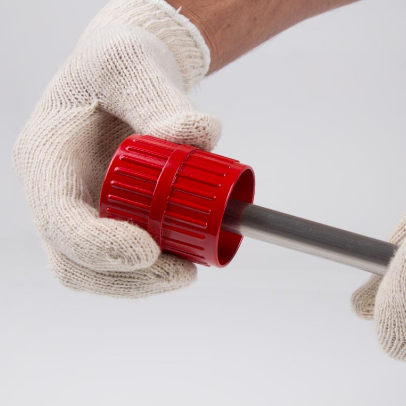
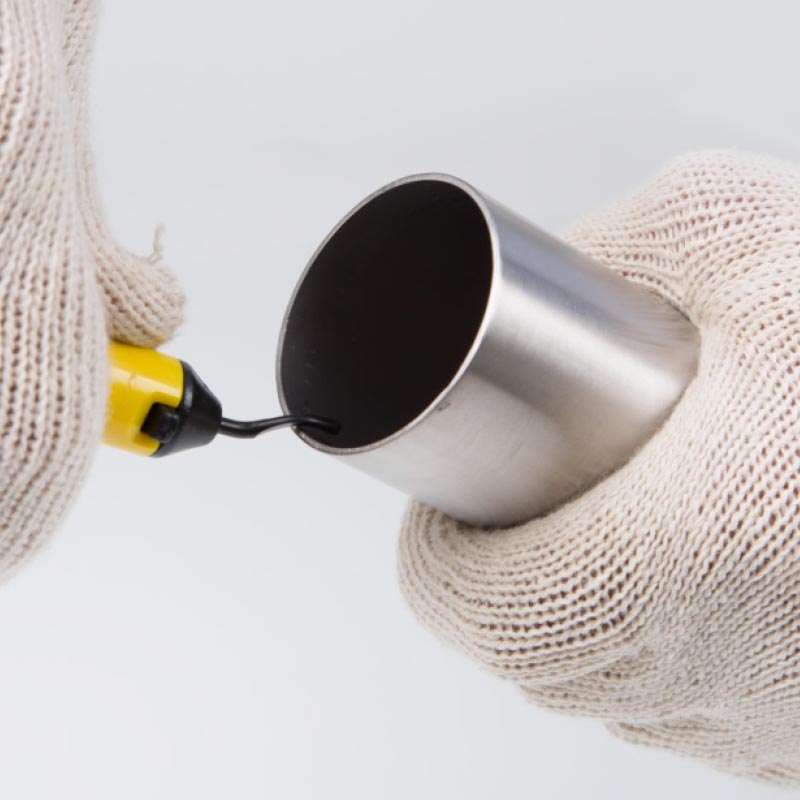
Deburring
Carefully deburr all pipe cuts inside and outside with a manual or electric deburring tool. Remove any cutting residue (swarf) to avoid damage to the O-ring upon insertion of the pipe to the fitting, ensuing a watertight joint.
3
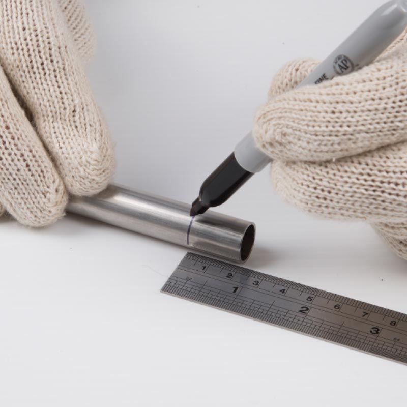
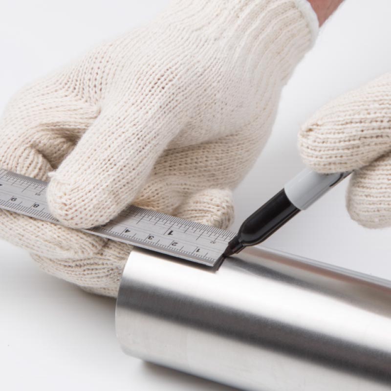
Assess mark insertion depth
Correctly inserted joints require marking the pipe with a fine-point felt-tip pen where it meets the fitting for verification of full insertion. The following depths apply:
15 mark at 21mm, 22 mark at 21mm, 28 mark at 24mm, 35 mark at 26mm
4
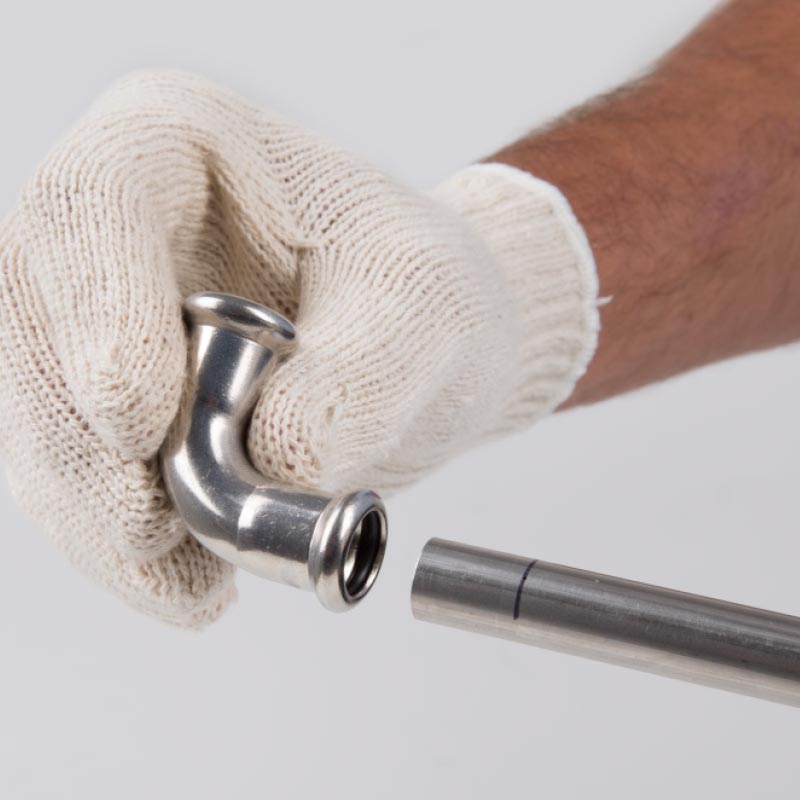
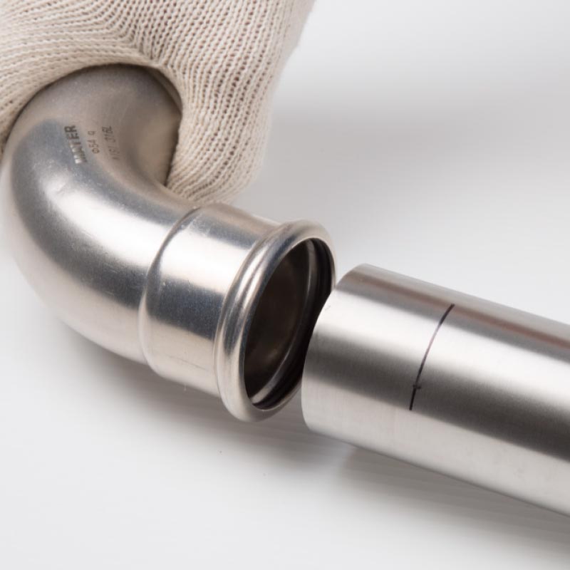
Assemble fitting on tube
Before assembling the fittings, check the positioning of the O-ring. If necessary, lubricate the O-ring with water or talc to ease insertion of the pipe. Never use oils, greases, glues or other similar substances. The pipe is inserted in the fitting with a slight rotating motion until it hits the stop. Check the pipe against the felt pen mark to ensure complete insertion.
5
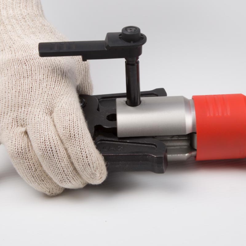
Press tool & jaw
Press tools are to be equipped with M-shaped profile jaw attachments or a pressing jaw which corresponds to the diameter of the fitting being pressed. Retract the lock pin, position the jaw in the tool head and fully engage the lock pin.
6
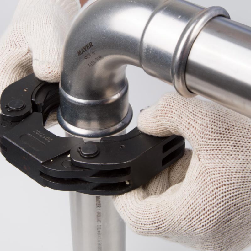
Position press jaw
Squeezing the two ends together to open the jaw. Position the jaw over the fitting, creating a perfect fit with the internal channel of the jaw around the toroidal seat of the fitting. Release the jaw and check for alignment.
7
Press joint
Squeeze the trigger to initiate the press cycle, holding it down for the full duration of the press cycle. The cycle must not be interrupted, and the tool will alert you (by beeping or the LED coming on) if the joint is unsuccessful. Press the reset button if the hydraulic ram is interrupted mid-cycle to manually override the automatic reset function. Check the LED warning light after each press to ensure sufficient batter power for the next press. More information is available in the tool’s trouble-shooting guide.
Sizes 42, 54, 76.1, 88.9 & 108
1
Cutting and deburring
Cutting and deburring pipes with these diameters is done in the same way as other sizes (see above).
2
Witness mark insertion depth
Correctly inserted joints are ensured by marking the pipe with a finepoint felt-tip pen. The following depths apply:
42 mark at 33mm, 54 mark at 36mm, 76.1 mark at 55mm, 88.9 mark at 63mm, 108 mark at 78mm
3
Assemble fitting on tube
Before assembling the fittings, check the positioning of the O-ring. If necessary, lubricate the O-ring with water or talc to ease insertion of the pipe. Never use oils, greases, glues or other similar substances. The pipe is inserted in the fitting with a slight rotating motion until it hits the stop. Check the pipe against the felt pen mark to ensure complete insertion.
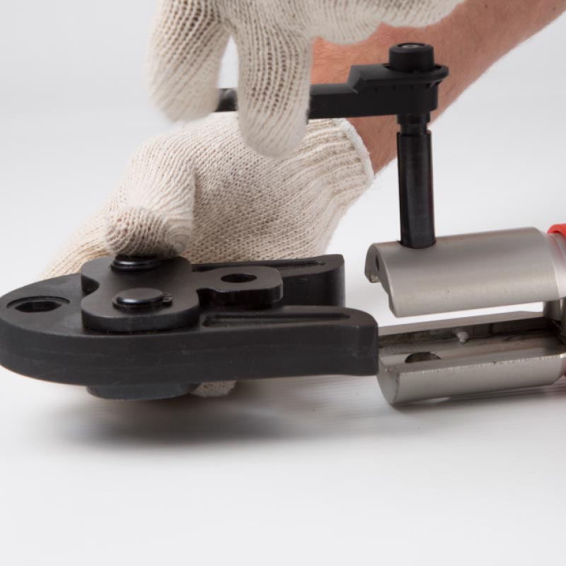
4
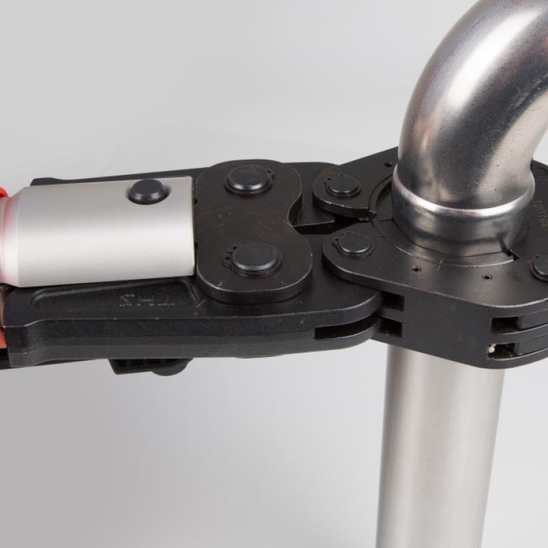
Assemble the adaptor to the press tool
5
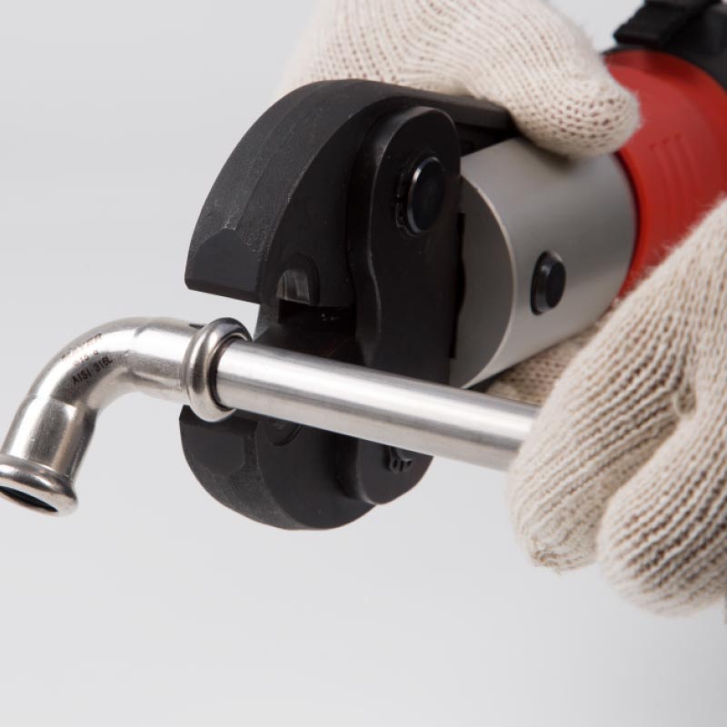
Attach press collar
Use the M-shaped profile pressing collar which corresponds to the diameter of the fitting being pressed. Open the jaw and position the jaw around the fitting.
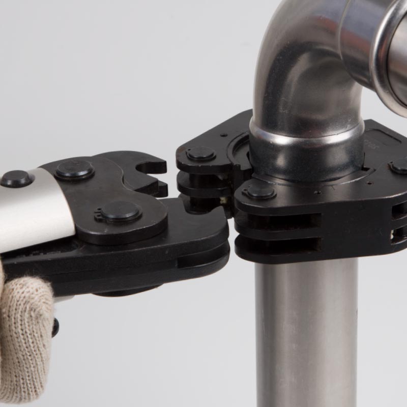
6
Connect press tool
Retract the lock pin, engage the adaptor and fully engage the lock pin.
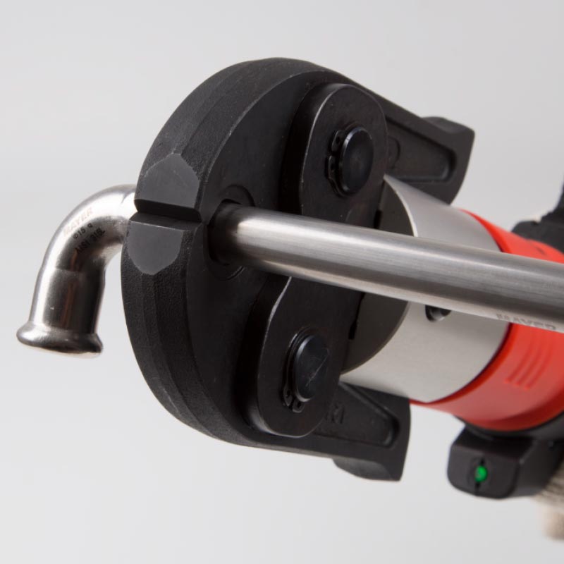
7
Press joint
Squeeze the trigger to initiate the press cycle, holding it down for the full duration of the press cycle. The cycle must not be interrupted, and the tool will alert you (by beeping or the LED coming on) if the joint is unsuccessful. Press the reset button if the hydraulic ram is interrupted mid-cycle to manually override the automatic reset function. Check the LED warning light after each press to ensure sufficient battery power for the next press. More information is available in the tool’s trouble-shooting guide.